
Views: 1390 Author: Uniwell Wirings Publish Time:2023-10-12 14:55:44 Origin: Uniwell Wirings
FOREWORD:WHY DO WE NEED TO DISCUSS CABLE SHIELDING ?
Through the usage of shielded cables, aim is to prevent existing noise sources from entering sensitive sub systems by targeting:
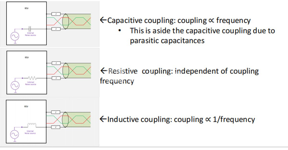
1. Reduction of capacitive coupled interferences due to electric fields
2. Elimination of common mode interferences through low impedance path
3. Eliminating inductively coupled magnetic field radiations with the shield
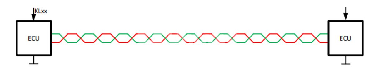
− With STP cables, this is attained through twisted signal conductor pairs
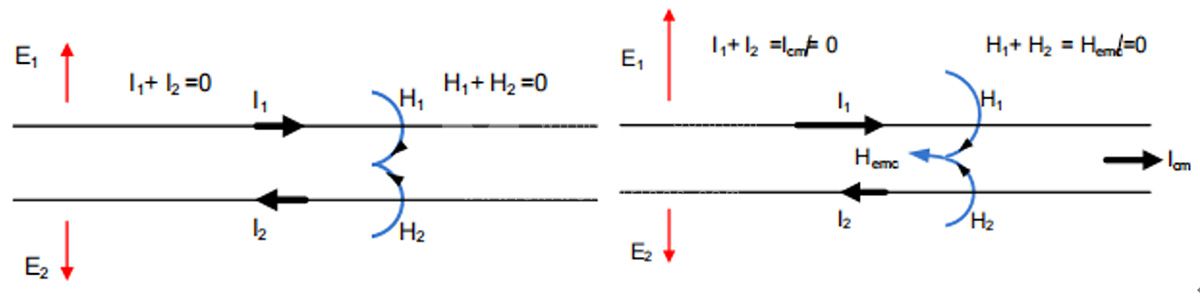
− However, with single conductor cables these radiations can be cancelled if there is an equal & opposite current flowing on shield versus signal
conductor
4. Attaining additional EMC margin adequate coupling attenuation (unbalance and screening attenuation)
Not directly connected to expectations of using shielded cables is:
− Prevention and elimination of coupled magnetic field noise sources. This is strongly linked to shield-ground loop area and how a shield-ground termination is implemented. Hence, cable shield effectiveness on magnetic field noise sources can be achieved through loop area reduction and proper shield termination
DIGITAL AUDIO BROADCASTING (DAB) FREQUENCIES IN THE PAST
Legacy bus systems e.g. LIN, CAN, CAN-FD, FlexRay only use frequencies below critical frequencies such as Frequency Modulation (FM) or DAB bands
- In the past, the Amplitude Modulation (AM) band was more critical with respect to EMC challenges Modern digital systems are accompanied by new challenges
- E.g. DAB, which requires high quality radio reception
- For an effective usage of DAB, radio antenna designers have increased the sensitivity of the corresponding antennas
Power spectrum in a rural area in Bavaria, DAB ~ 15dB lower than FM
station
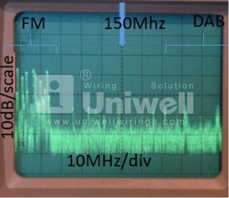
IN THE PAST- DAB FREQUENCIES WERE NOT AFFECTED
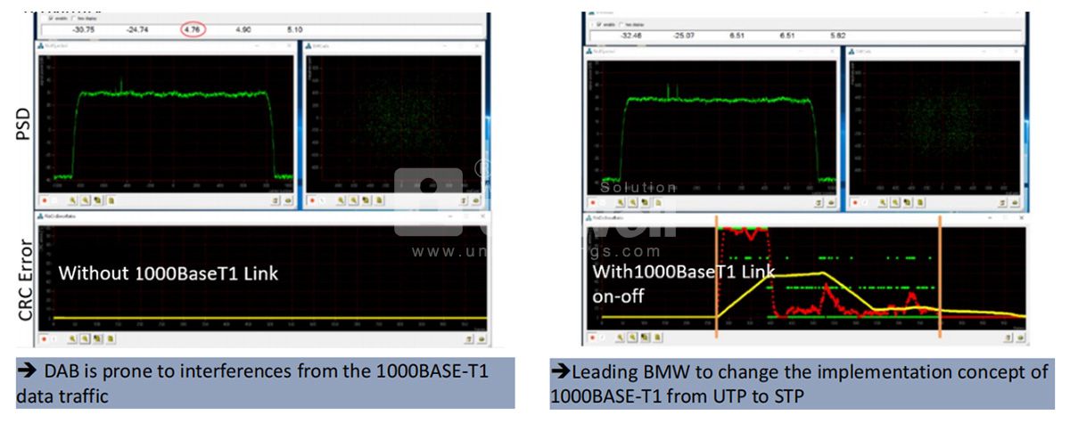
The following figures display the impact of operating a DAB test receiver and a 1000BASE-T1 UTP data link in close proximity:
MULTIPORT CONNECTORS – PAST VERSUS PRESENT
Past generation of multiport connectors
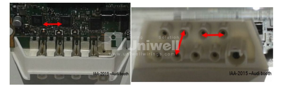
Present generation of multiport connectors
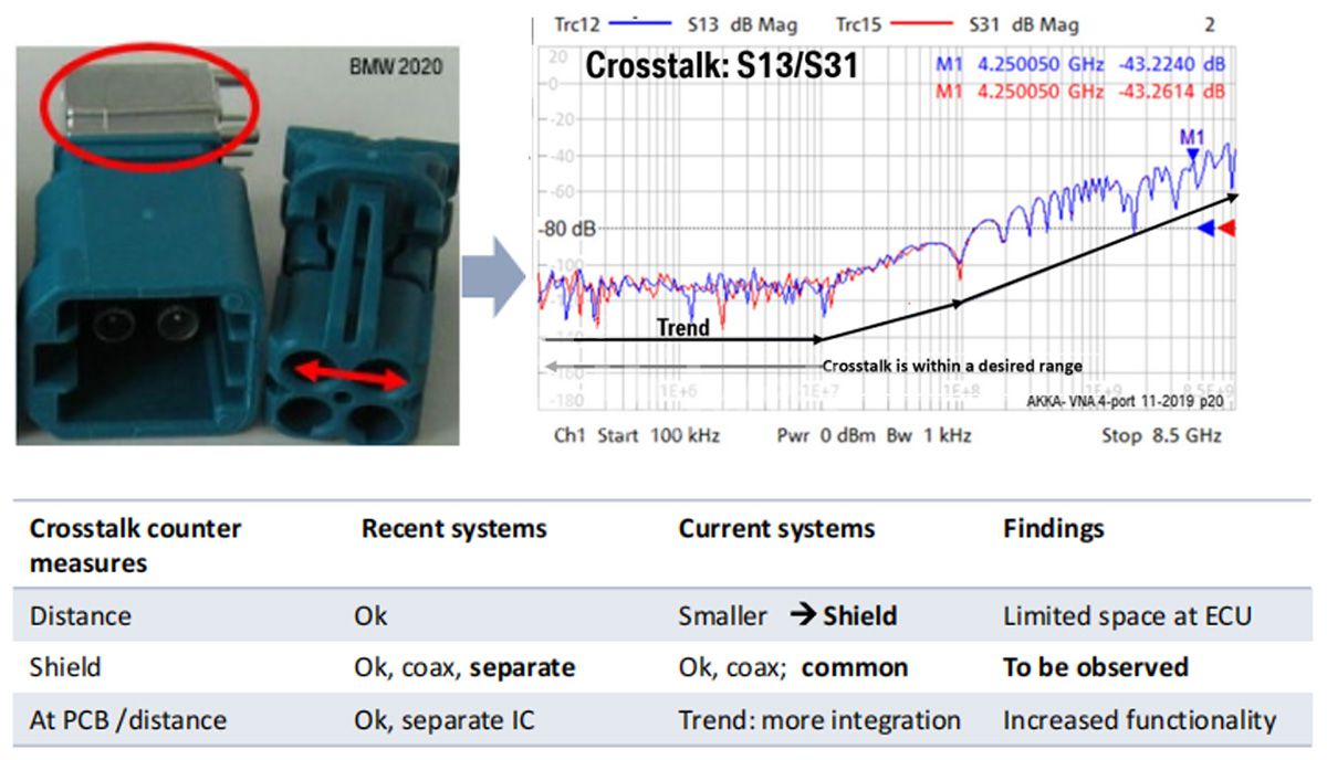
Almost no crosstalk effects below 10MHz; →no issue for classic bus system
Increase of 10dB/decade from 10 to 100MHz →only small impact for 100BASE-T1
Increase of 15 to 20dB/decade above 100MHz →impact for 1000BASE-T1 and SerDes
PREVIOUSLY: CONDUCTOR PAIR SYMMETRY WAS USED FOR EMI PREVENTION
Most of the EMC issues are tackled through usage of a twisted and differential pair cable
- A defined cable topology was needed to partially address high speed signal transfer requirements
100BASE-T1:
•This works fine since the Power Spectral Density (PSD) is above AM band and below FM Band.
•It also uses the impact of conductor pair symmetry as the main method of EMI prevention
1000BASE-T1 :
• Goes to the limits of the symmetry approach for cables, connectors & common mode chokes: crosstalk gets a new, major limiting parameter.
• Nyquist Frequency of 375MHz
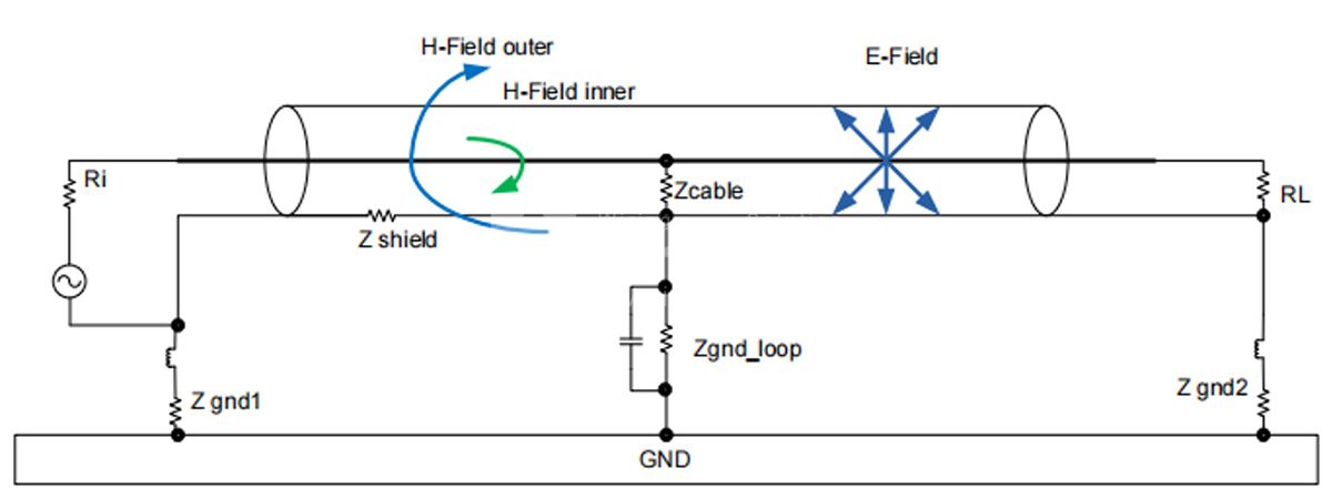
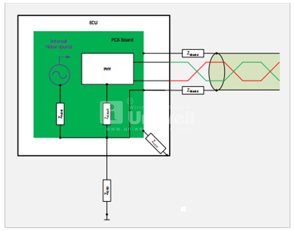
WHICH CABLE SHIELD-GROUND NOISE COUPLING MECHANISMS ARE TO BE EXPECTED?
• Noise generated internally within the ECU
• Direct noise source coupling to ground
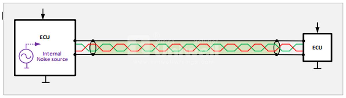
• Noise coupling via ground distribution
AN EXAMPLE OF INDUCTIVE NOISE COUPLING ON CABLE SHIELD
• Noise coupled to shield from a source along the channel
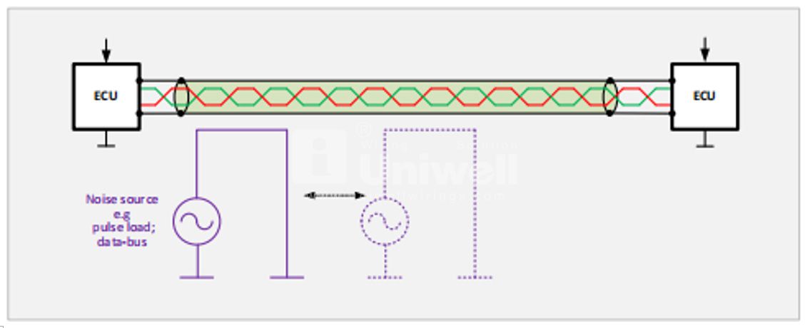
• Test setup
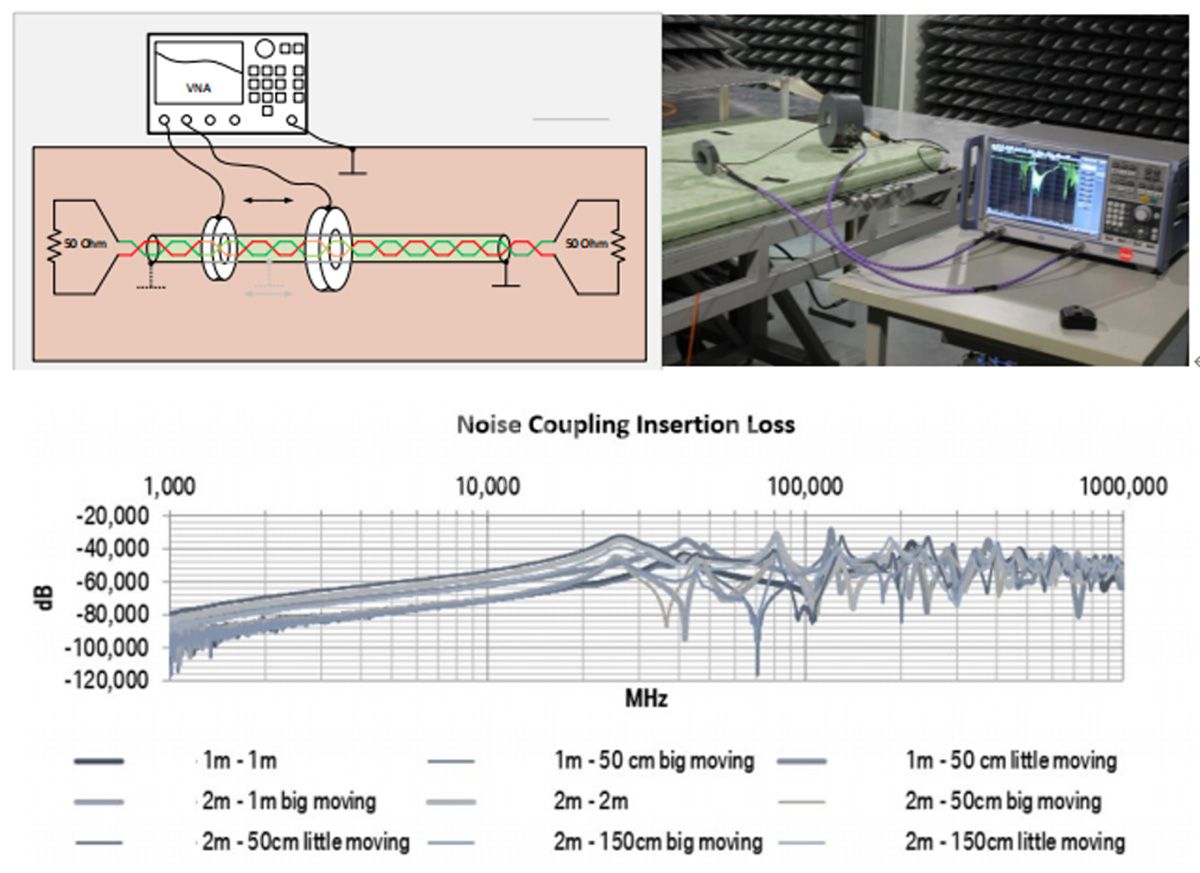
Noise coupling increases up to a range of ~25MHz;
• It then remains at a certain base level, but with resonances
• The resonances vary with cable length as well as the length of its ground line connection; as second order of the noise source
• Additional ground clamps shift the resonances
DO SHIELDED CABLES PREVENT GROUND RESONANCE ?
EMC Test Setup
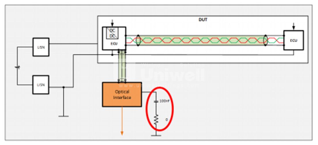
Initial assessment of the test results → no abnormalities are observed
Then, with an optical interface EMI noise above the limit within
the kHz range is observed
A weak resonance system with noise up to the MHz range is
stimulated by a DC/DC converter within an ECU by adding a Internal ECU noise should be kept low
• Pre-check the resonance / impedance behavior of the ground system
• Cable shielding does not prevent nor eliminate ground resonance
PRIORITIZING SYSTEM GROUND CONCEPT DEFINITION
For an early prevention of cable shield interferences, It is essential to define a specific system grounding configuration in the initial system design phase
General complete system ground scheme
− Defining grounds based on signal
type, frequency and voltage levels
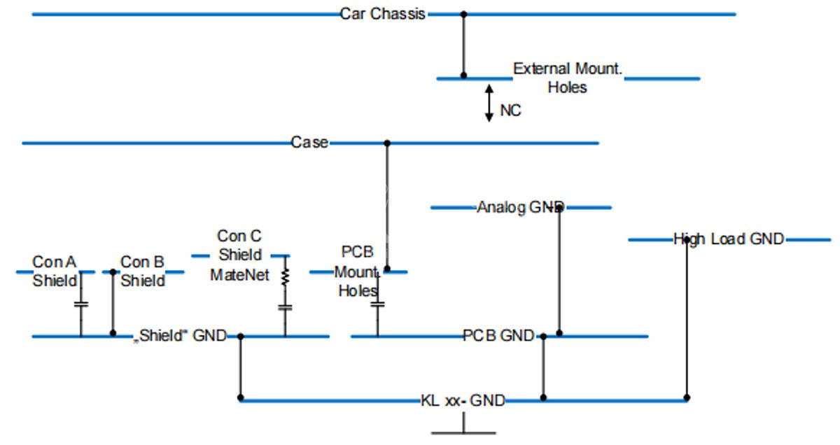
Defining a grounding scheme within a sub-system
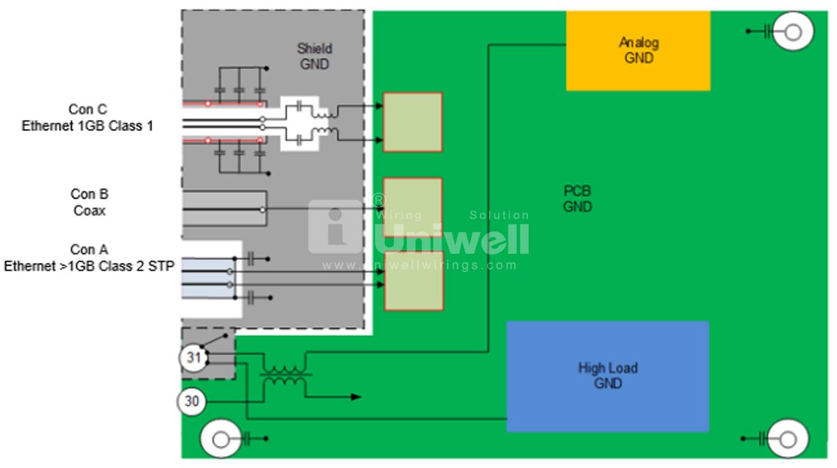
There has to be a correlation between system versus sub-system ground implementation
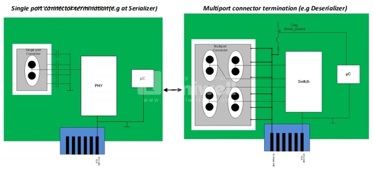
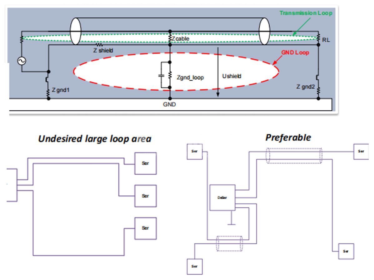
KEY CONSIDERATIONS FOR CABLE SHIELD TERMINATION & GROUND LOOPS
• AC coupling capacitor(s) should be used on the second end of the shield
- This aids in shield connection retention at high frequencies and breaking the ground loop at lower frequencies
- Adaptations are required for ECU-ECU and for Display
connections
• Shield-ground Low impedance path is essential for maximum
shielding benefits
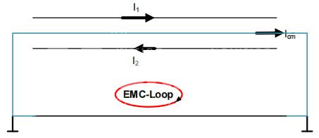
• A shield-ground loop acts as either a receiving or transmitting monopole antenna Conducted & radiated EMI coupling
• Reduction of the shield-ground loop area to the desired “transmission loop” range aids in minimizing the magnetic field strength within the loop and hence the induced noise current
CONCLUSION
• Being able to use shielded cables is essential for current and future high data rate communication systems.
• However, it is of essence that the correct and a well planned system implementation approach is incorporated. This is to commence by pre-defining an overall system grounding configuration and based on that defining a general corresponding shield-ground approach.
Takeaways:
1. Generally, ground planes are not ideal and therefore cause impedance variations
2. Cable shielding has minimum effect on inductively coupled noise but rather effectively addresses electric field noise sources
3. It is essential to define a system grounding configuration in the initial system design phase
− Single point shield-grounding within a sub-system also favors elimination of common ground impedance
− Multipoint system grounding scheme tends to operate better in high frequencies
4. Cable shielding effectiveness is impacted by the method of its termination
− Low impedance shield-ground paths are essential for maximum shielding benefits
5. Cable shielding implementation should also target the root noise sources

We are always looking for new global partners and distributors - Get in touch
